MAGNIFICATION
A small subject made LARGE
Optical inspection of fiber optic connectors for cleanliness, scratches, fractures, pits, and other surface anomalies has become a very important issue, especially in light of 10 Gbit and higher data rates being introduced in our optical networks. In order to see connector endface defects, a fairly high order of magnification is necessary. How high is still a subject of great debate between different groups. Typical discussed values are 200X to 400X. If the magnification is too low, certain contaminants and scratches cannot be observed. If the magnification is too high, connectors will be rejected unnecessarily. However, there is another subject which must be defined in order for an optical inspection unit to deliver the order of magnification necessary to meet the criteria established by the end user. And that subject is: How do you define magnification?
Various manufacturers of Optical Inspection Instruments are making claims of magnification without specifying such parameters as display size or resolution. The following information is presented to give the reader a clear understanding of magnification, resolution, field of view and other optical criteria.
For purposes of this discussion, we want to look at three basic types of magnification. For lack of a more technical name, we shall refer to them as OPTICAL, ABSOLUTE, and ELECTRONIC MAGNIFICATION
OPTICAL MAGNIFICATION
Referring to Fig. 1, we will refer to the core/cladding portion of the end face of the fiber optic connector as the TARGET. The OPTICAL MAGNIFICATION is the amount that the TARGET is magnified by an optical lens or lenses which are situated between the TARGET and the CCD chip, or camera. The lens(es) magnify the 9/125 micron diameter of the TARGET and project the image onto the face of the CCD chip. In a typical Optical Inspection Instrument the OPTICAL MAGNIFICATION at this point can be from 15X to 25X depending on the ABSOLUTE MAGNIFICATION you are trying to achieve. This OPTICAL MAGNIFICATION determines what percent of the CCD chip is occupied by the TARGET and hence, what the ultimate resolution of the TARGET is. The greater percentage of the CCD chip occupied by the TARGET, the higher the resolution. Also, more pixels in a CCD chip of the same size result in a higher resolution. An example of a CCD chip used in an Optical Inspection Instrument is a 1/3 inch device in a 512 x 582 array, or approximately 298,000 pixels.
 |
<<<<<<<<<<<<<< |
 |
<<<<<<<<<<<<<<< |
|
| CCD CHIP | LENS(ES) | TARGET | ||
| Fig. 1 |
The entire face (approximately) of the CCD chip constitutes the Field of View that the observer sees when looking at a video display. The greater the TARGET size on the CCD chip, the greater the TARGET size on the display. Referencing Fig. 2, an important point to note is the ratio of the size of the TARGET to the size of the display remains the same regardless of the size of the display. In other words, that ratio is the same whether using a 9 inch video monitor or a 27 inch monitor. By observing that ratio, we can get an idea of how much OPTICAL MAGNIFICATION the inspection device has assuming CCD chips of the same physical size.
 |
 |
|||
| SMALL DISPLAY | LARGE DISPLAY | |||
| Fig. 2 |
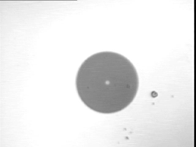
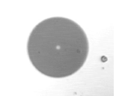
By looking at Fig.3 we can see that the image from the inspection device on the right has a larger OPTICAL MAGNIFICATION than the image from the inspection device on the left. Again, this is based on both inspection devices using the same size CCD chip.
 |
 |
|||
| 22X OPTICAL | 44X OPTICAL | |||
| Fig. 3 |
ABSOLUTE MAGNIFICATION
ABSOLUTE MAGNIFICATION of the TARGET is obtained by simply dividing the diameter of the TARGET (core/cladding image) as measured on a display by the diameter of the unmagnified fiber as seen at the connector endface, which is 125 microns. 1 micron is equal to 0.001 millimeters and 1 inch equals 25.4 millimeters. Therefore, 1 micron equals .00003937 inches and 125 microns (the diameter of the core/cladding image) equals.0049125 inches. For 200X ABSOLUTE MAGNIFICATION multiply .0049125 times 200 and the result is 0.98 inches, or approximately 1 inch. This is exactly what the core/cladding image or TARGET diameter from the example above measures when displayed on a 3.8 inch monitor. If this same image is displayed on a 5 inch monitor, it measures approximately 297X. Therefore, once again referencing Fig. 1, one can see that the larger the monitor, the larger the ABSOLUTE MAGNIFICATION. However, keep in mind that different Optical Inspection Instruments will produce different core/cladding image diameters on the same display depending on the amount of OPTICAL magnification they use. The higher the OPTICAL MAGNIFICATION, the greater the size of the TARGET on the display and the higher the resolution.
ELECTRONIC MAGNIFICATION
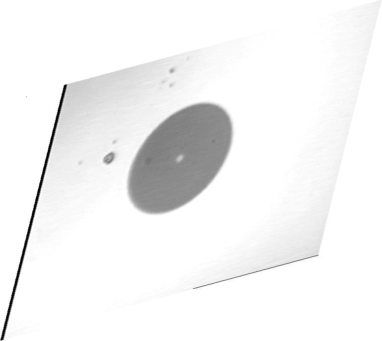
The third type of magnification to be aware of is called ELECTRONIC MAGNIFICATION. An example of this type of magnification can be seen when you “zoom” in on the TARGET on your computer. This is accomplished by masking or “cropping” out part of the image and then re-displaying the remainder of the image over the entire face of the display. This results in a larger TARGET being presented on the display as shown in Fig. 4 which should be noted is very similar to that shown in Fig. 3. As the TARGET becomes larger you begin to see the individual pixels. ELECTRONIC MAGNIFICATION has no effect on resolution.
 |
 |
|||
| NORMAL | ZOOMED | |||
| Fig. 4 |
SUMMARY
Most users of Optical Inspection equipment do not fully understand magnification. Most will say they want between 200X to 400X but have little if any idea what that translates to in image size. The following points should be very helpful in clearing up issues of magnification:
1. ABSOLUTE MAGNIFICATION should be the type of magnification specified.
2. ABSOLUTE MAGNIFICATION MUST reference the size of the monitor being used.
3. ABSOLUTE MAGNIFICATION is the diameter of the image being displayed divided by the diameter of the object being magnified.
4. ABSOLUTE MAGNIFICATION does not change the resolution of the image.
5. OPTICAL MAGNIFICATION is the diameter of the image projected onto the CCD camera chip divided by the diameter of the object being magnified.
6. OPTICAL MAGNIFICATION improves the resolution of the image.
7. ELECTRONIC MAGNIFICATION is obtained by masking off part of the displayed image and then re-displaying that image over the entire monitor. This is in essence “stretching” the image over a larger surface.
8. ELECTRONIC MAGNIFICATION does not change the resolution of the image.
9. RESOLUTION is a factor of the number of pixels contained in the image being displayed on the monitor. The more pixels in the image, the higher the resolution.
10. FIELD of VIEW is determined by how much you can see of the object being magnified. The greater you magnify the object, the less the field of view. You CANNOT make the core/cladding image larger and at the same time see more of the endface of the connector.
11. FIELD of VIEW is not changed by ABSOLUTE MAGNIFICATION.
12. FIELD of VIEW is changed by OPTICAL and ELECTRONIC MAGNIFICATION
Copyrighted Nov. 26, 2000 Lyel R. Upshaw
